#Gas #ACS #Plumber Flame rectification is one of the lesser understood types of flame supervision devices that we cover on gas training. At National Gas Centre for Excellence, students often get confused when we talk about converting voltage and current via a flame as if its some sort of wizardry.
When we break down the process, it becomes a little easier to understand. At some point, we will all come across a faulty boiler indicating a flame failure fault or an ionisation fault (an EA or FA fault on our Worcester 30i ERP for example). One potential cause of both faults could be poor or no flame rectification.
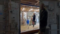
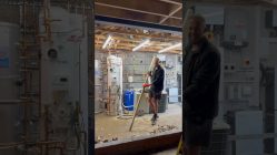
Most engineers are familiar with the firing sequence of a boiler. The PCB sends power to the gas valve and spark generator to create a flame. There is another circuit being established by the PCB that less engineers are familiar with.
The PCB sends a moderate AC voltage to the flame rectification probe (usually around 100v ac however this can vary). When a flame has been established at the burner, the flame engulfs the rectification probe and conducts the voltage, rectifying (changing) it from AC to DC current in the process. The DC voltage then travels back to the PCB via another wire (sometimes an earth wire) and completes the circuit.
Once the PCB registers a DC current being present, it knows that a flame has been established and stops sending power to the spark generator. Should the PCB stope receiving DC voltage / current for any reason, it will stop sending power to the gas valve, stopping the supply of gas to the main burner in the process. After a number of failed ignition process’, the PCB will go to lock out and present an ignition or ionisation fault.
It is the process of the voltage changing from AC to DC and the board receiving the DC current that monitors the presence of the flame. The only way in which the PCB can receive DC current is via a flame completing the circuit at the main burner.
We can use out multimeter to test for DC voltage by connecting it in series between the rectification probe and the rectification lead. Any DC voltage can then pass through the multimeter, being registered in the process. We can also use the micro-amps setting to do this if we have a multimeter with this function available.
If a boiler goes to an ionisation fault on its ignition sequence, then it is likely to be caused by a faulty component like a gas valve, ignition probes or spark generator, however if we can see or hear a flame being established, then we should also test to see if the rectification probe is conducting the voltage and subsequently being registered by the PCB.
If the boiler is going to fault later on in its operation sequence, then its possible that the DC voltage / current is being lost at some point. Potential causes for this include a poor flame (vitiated), a MIN burner setting being too low or a poor connection on the rectification circuit.
Should anyone wish to learn more about fault finding or other courses offered by National Gas Centre for Excellence, please contact us on 01924973260 or by visiting our website at www.NGCFE.co.uk .